

Introduction
Given the pressures to reduce the length of time to complete
a class, many schools are reducing the length and amount of
time classes meet. Since customer service is a key part of
product delivery it is understandable schools are trying to
meet this demand. On the other hand businesses still want
graduates that have a strong fundamental base of knowledge.
At times both of these customer demands are opposing views
that must both be satisfied if schools want to be successful.
Being an IT professional by day and an adjunct professor by
night I have seen how both of these opposing views have valid
arguments. One of the goals I have is to bring students to the
highest levels in the shortest amount of time. This way I might
be able to hit both of these goals and sacrifice very little.
The challenge comes when a class curriculum has very high level
of rigor but the class timeline is very short. This is the
position many of us who teach run into. It is in this environment
where I have spent a lot of time learning how to teach one of the
hardest networking subjects in a rather successful way. In no way
should this be taken as “the way to teach” subnetting. This is just
a process I have developed that has helped in many ways to get the
point across in a very short period of time. The goal of this paper
is to have the process documented for my students as well as anyone
else who wants to see a new view on how to subnet.
Basics
Before looking at subnetting there are some basics that need to be
covered before we go on. For people who have a good idea of binary
and subnet masks this section may be skipped. However there are some
short cuts I use in subnetting that will reference back to some of
these basics. To start I want to introduce the values of eight bits.
As we know computers speak in a language called binary. This is where
each numeric column represents a one or zero. In short counting in
binary is almost like counting by doubling the previous column. The
following shows the values of each of the columns for eight bits.
128
64
32
16
8
4
2
1
Figure 1
For example a decimal value of 156 looks likes 10011100 in
binary. Another way to think of this is 128 + 16 + 8 + 4.
Learning to convert from binary to decimal and decimal to
binary is an important skill and needs to be developed. It is
a rather simple skill, but just takes time to convert back and
forth. Just as a note the valid values for eight bits are 0 to 255.
Network addresses consist of 32 bits. These 32 bits are
represented in a human readable format called a doted quad.
That is four eight bit numbers separated by three periods.
Each of the four values is called an octet because that value
represents eight bits. An address would like something like:
XXX.XXX.XXX.XXX
A network mask is used to separate the network bits from the
host bits. For a network mask to be valid it must have all ones
in a contiguous sequence followed by zeros in a contiguous sequence.
The ones start at the highest bit going down to the lowest bit, once
a zero is encountered the rest of the bits are all zeros. This leads
to a simple calculation for the number of total hosts on a network,
H = 2N Where H equals the total number of hosts on the network and
N equals the number of host bits in the network mask. For example
if there are 8 host bits in the network mask, then there are a total
of 256 hosts on the network (28 = 256). Knowing that the network and
host bits have to follow the contiguous rule, there are only nine
different patterns that an octet in a network mask can be. These are:
# Network Bits
Binary
Decimal
0
00000000
0
1
10000000
128
2
11000000
192
3
11100000
224
4
11110000
240
5
11111000
248
6
10000000
128
7
11111110
254
8
11111111
255
Figure 2
Keeping these values in mind a subnet mask is simple to define. The
subnet mask octet is 255, 0, or one of the decimal values in the above
table. 255 values are always on the left, 0 values are the right, and
the table value in the middle. For example a network mask can be:
255.255.128.0, 192.0.0.0, or 255.255.255.224. In all these examples the
subnet mask has all the ones followed by all zeros.
In a Variable Length Subnet Mask, VLSM, is a network address is depicted
using a prefix number after the network address and is separated from the
network address by a slash, “/”. This prefix value represents the number
of bits used for the network. For example: 192.168.1.0/24 show that the
network address is 192.168.1.0 and 24 bits of the address are used for the
network. By now it should be clear that a valid value for a prefix is from
one to thirty-two. Since the prefix shows the number of bits for the network
subtracting this value from 32 will tell how many bits are used to show the
number of hosts in the network. Using the example above would include eight
bits for the number of hosts on the network.
Address
192
168
1
0
Binary
11000000
10101000
00000001
00000000
Mask
255
255
255
0
Binary
11111111
11111111
11111111
00000000
Figure 3
The above table shows what the network address and subnet mask looks
like in both decimal and binary. An inspection of the fourth row
shows clearly that the network consists of ones for the network
and zeros for the hosts in the subnet mask.
Logical And
Before proceeding too far, an understanding of a logical AND
operation has to be established. All logical operations take
two operands and will return a result of true or false. In
computer language a true equates to a value of one and false
equates to a value of 0. The outcome of a logical AND can be
expressed in a simple truth table.
0
1
0
0
0
1
0
1
Figure 4
The logical AND operation is defined as two true values will equate to
a true value, any other combinations of values will equate to false. Do
not undersell this process for without doing an AND calculation there
will be no way to calculate the network address. Please refer to Figure
3 if there are any questions. For example binary values of 101 (decimal
5) anded with a binary value of 011 (decimal 3) returns a binary value
of 001 (decimal 1). A clearer way of looking at this is:
101
011
----
001
In the first column, on the left, the result of 1 and 0 is 0.
In the middle column the result of 0 and 1 is 0. In the first
column, on the right, the result of 1 and 1 is 1. Thus the
binary outcome is 001, or decimal 1.
Calculating Network and Broadcast Addresses
Calculating Subnet Masks
If the network and broadcast addresses are found first it
is very easy to calculate the usable host range. Since the
first address of a network is the network address and the
last address of the network is the broadcast address it
should be obvious why it is important to find these two
addresses. The broadcast address is the address used to
communication to all hosts on the network. It should also be
noted that these two addresses are not allowed to be assigned
to any hosts on the network. In most cases, an address is written
in prefix notation, so the first step is to convert this address
into an address and subnet mask. For this exercise we will use
the address 192.168.250.23/22. The question that has to be answered
is if this address is a host address, network address, or the
broadcast address.
The first step in calculating the subnet mask is to find the full
octets that are part of the network mask. This is done by dividing
the prefix number by eight and looking at the number of times eight
goes into the prefix number, forgetting the fractional part for now.
A prefix value of 22 has two complete octets in the subnet mask that
are all ones, 22 / 8 = 2 with six left over. A prefix of 22 notates
22 network bits which will leave 10 bits for host bits. This is
because a network address is comprised of 32 bits so 32 – 22 = 10.
Using the same process to find the complete octets for the network
bits it can be concluded that there is one complete octet of host
bits, 10 / 8 = 1 with a remainder of 2. What is now known is that
there are two complete octets in the network mask and one complete
octet in the hosts. The following diagram shows each octet (spaces
between) and marks the network from the host bits.
Network Host
11111111 11111111 11111100 00000000
The basics looked at above show that network ones start at the left and
host zeros start at the right of the subnet mask. Using this information
it can be concluded that the network mask octets know are:
255.255.???.0
The focus now changes to be on the third octet. Given that the subnet
mask can be made up of 255, 0, or one of the values from the table in
Figure 2 it is clear that the next step is to select the proper values
from the table to insert into the third octet. In the above calculations
it can be seen that this octet contains six network bits. This
information is from the six bits left over from the division used to
calculate the complete octets needed for the network bits. Referencing the
table in Figure 2 six bits will give an octet value of 252. Applying this
last piece of subnet mask the completed subnet mask now looks like:
255.255.252.0
Calculating Network and Broadcast Addresses
The next step is to find the network and broadcast addresses.
This can be done at the same time because three simple rules
can conclude three of the four octets in both of these addresses.
This is important because it reduces the risk of making a
mathematical mistake by 75%. The first goal is to calculate the
network address. Once this is found the broadcast address is
calculated from the network address. With the knowledge of both of
these addresses the first and last usable host addresses are very
simple to find.
The first of these rules is wherever there is a 255 in the
network mask; the network address is the same as the host
address. Continuing with the current example, a host address
of 192.168.250.23 with a subnet mask of 255.255.252.0 leads
to the knowledge that the first two octets in the both the
network and broadcast address is 192.168. This is because any
number that is anded with 255 returns a value equal to itself.
The second rule is used to find the third octet in the network
address. Looking at the table in Figure 4 it is clear that any
number anded with 0 will equate to 0. This means that any subnet
mask octet that is 0 will return a 0 for the network address.
Using the current example the last octet would be 0 because the
0, from the subnet mask, anded with the23 of the last octet of
the host address would result in a value of 0. So at this point
the three known octets of the network address are:
192.168.???.0
The third rule is used to find the third octet in the broadcast
address. This rule is very simple; any octet with a 0 in the
subnet mask will result in a value of 255 for the broadcast
address. Again the current example would yield a value of 255
for the fourth octet because the network mask is 0. This means
that the three known octets of the broadcast address are:
192.168.???.255
Up to this point finding the network and broadcast addresses
turn out to be a very simple process. The last step it to
calculate the final octet to both addresses. This is where the
process gets a little tricky. The first step is to find the
network octet. This process is done by converting both the subnet
mask octet and the host address octet into binary. This is the
hardest part because the known decimal value has to be converted
into binary. In this case the host address octet is 250. This value
in binary is 11111010. The next step is not as hard, in that we can
use the table in Figure 2 to help find the value we are looking for.
The value of the subnet mask is 252. Using the lookup table a binary
value of 11111100 is found. To help make the logical anding a little
easier, write out both values one under the other so that the eight
bits align. Then do the anding bit by bit. The calculation looks like:
11111010
11111100
------------
11111000
The answer to the logical AND is 11111000 in binary, which is a
decimal value of 248. This is the value of the unknown octet in
the network address. This also completes the network address.
So a host of 192.168.250.23/22 has a network address of 192.168.248.0.
At this time it is clear that the host address that has been given
is not a network address, however it is still unknown if the host
address is the broadcast address (or not even part of the network).
The final step is to find the broadcast address for the network.
This is the missing octet of the broadcast address. Calculating
the broadcast address is rather simple, however it is not as obvious
as calculating the network address. The first step is to find how
many hosts are on the network, using Figure 1 to find the bit value
of the last 1 in the network mask then subtract one from that value.
For example if the last network bit has a value of 128, then there are
127 hosts on the network (128 – 1 = 127). In the current example the
last network bit has a value of 4, so there are 3 hosts (4 – 1 = 3).
The second step is to add the number of hosts to the network address
octet. This is because the broadcast address is higher than the network
address. In the current example the number of hosts, 3, is added to the
network octet, 248, which results in a value of 251. This gives a
broadcast address of 192.168.251.255 for the current network.
Find First and Last Usable Host Address
Now that both the network and broadcast addresses has been determined,
the last addresses to learn are the first and last usable host addresses.
Both these address are extremely simple to calculate since the other two
addresses have been found. The first usable address is always one address
higher than the network address, and the last usable address is always
one less than the broadcast address. These are calculated by adding one
to the last octet of the network address and subtracting one from the last
broadcast address. To complete the current example the first usable address
is 192.168.248.1 and the last usable address is 192.168.251.254. Now all
four important addresses have been calculated.
Creating More Than One Network
Calculating Network and Host Bit Amounts
Many times there is a need to divide a network and use as few IP as
possible. In this case there are a couple of things done before
calculating the four important addresses shown above. First of all
users will define the network based off of the number of network users
to be supported. However there is an issue with this, it does not
include the space needed for the network address and broadcast address
so two must be added to the number of users for each network. For
example if a user defines the need for four networks, with a base address
of 192.168.1.0/24, with one network having 10 users, the second network
having 13 users, the third network having 22 users, and the last network
having 5 users, two must be added to each of these numbers. In this example
the four networks would include total hosts of 12, 15, 24, and 7.
Since the process of subnetting is sub-dividing it needs to be kept in
mind that networks must get smaller not larger. So the total network
host counts must be arranged in descending order. That means from largest
to smallest. In the current example that would mean that the networks will
be divided in the order of 24, 15, 12, and 7. If this step is not completed
correctly, then there will be problems dividing the network with the smallest
number of wasted IP space as possible.
Now that the total number of hosts for each network has been determined,
the next step is to divide the network. The process of dividing the network
comes down to “borrowing” bits. This is a process where host bits are
borrowed to create and new network. The following trick was taught to me by
a very good instructor and has become a very good visualization of the process.
Using the teeter totter the goal is to balance no more than eight bits.
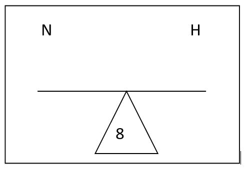
Starting with the host bit count; answer the question of how many bits are
needed to include at least the number of required hosts. In the current
example the first network being created requires 24 hosts, so only five host
bits are needed (31 hosts). To balance the teeter totter there will have to
be three network bits. The diagram will look like:
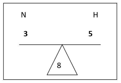
Now that the teeter totter is complete the information can be used to determine
the new network prefix. The three network bits are added to the base network prefix
of 24 giving the new network a prefix of 27, or 192.168.1.0/27. Using the process
defined above the first network looks like:
Network Mask
Prefix
Mask
Broadcast
First Host
Last Host
192.168.1.0
27
255.255.255.224
192.168.1.31
192.168.1.1
192.168.1.31
The next network needs to have 15 hosts. To conserve space rather than using
the next network of 31 hosts, the teeter totter will be rebalanced to look like:
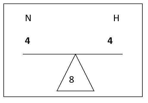
This will allow exactly 15 hosts for the network. Again add the network bits
to the baseline prefix of 24 and now there are 28 network bits. So the second
network looks like:
Network Mask
Prefix
Mask
Broadcast
First Host
Last Host
192.168.1.0
27
255.255.255.224
192.168.1.31
192.168.1.1
192.168.1.31
192.168.1.32
28
255.255.255.240
192.168.1.47
192.168.1.33
192.168.1.46
The third network requires 12 hosts. In this case the same network mask can be
used as for the previous network. Now the networks look like:
Network Mask
Prefix
Mask
Broadcast
First Host
Last Host
192.168.1.0
27
255.255.255.224
192.168.1.31
192.168.1.1
192.168.1.31
192.168.1.32
28
255.255.255.240
192.168.1.47
192.168.1.33
192.168.1.46
192.168.1.48
28
255.255.255.240
192.168.1.63
192.168.1.49
192.168.1.62
The four, and final, network needs to have 7 hosts so the next network can
be divided which will create a new teeter totter which will look like:
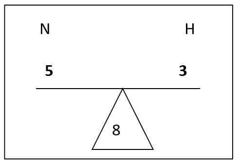
This will allow exactly 7 hosts for the network. Again add the network
bits to the baseline prefix of 24 and now there are 29 network bits.
So the final network looks like:
Network Mask
Prefix
Mask
Broadcast
First Host
Last Host
192.168.1.0
27
255.255.255.224
192.168.1.31
192.168.1.1
192.168.1.31
192.168.1.32
28
255.255.255.240
192.168.1.47
192.168.1.33
192.168.1.46
192.168.1.48
28
255.255.255.240
192.168.1.63
192.168.1.49
192.168.1.62
192.168.1.64
29
255.255.255.248
192.168.1.71
192.168.1.65
192.168.1.70
Looking at the completed table it is clear that all four networks can fit
into less space using this method than if each network was given a 24 bit
prefix. When space cannot be freely wasted this will allow networks to be
created wasting the least amount of IP space.
Conclusion
The approach shown in this paper is just one way to look at subnetting.
The hope is to show what I think is a simple way to subnet a network
with lowest risk of error. As I stated before there are many ways to
subnet, but this is one I have had very good success using in both in
class and in business to teach subnetting.